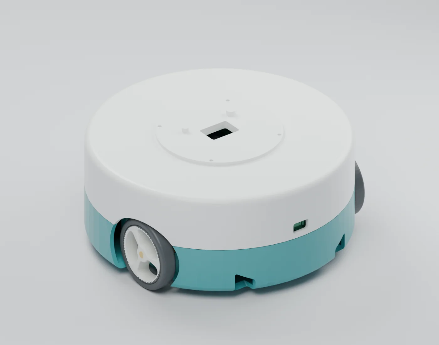
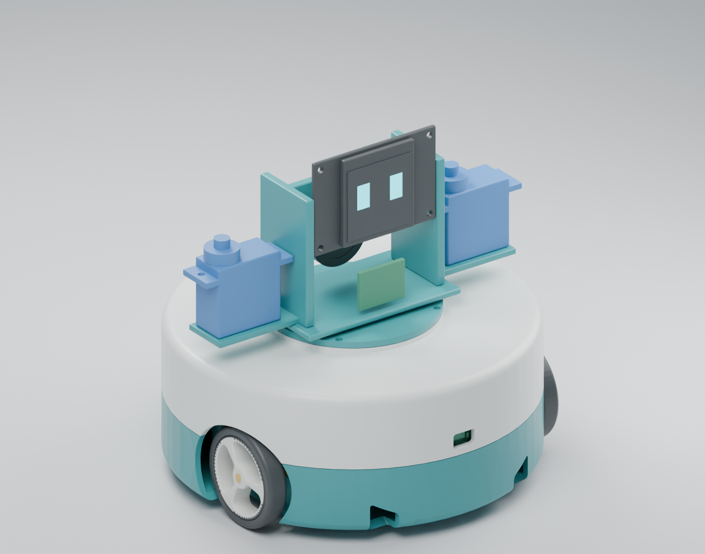
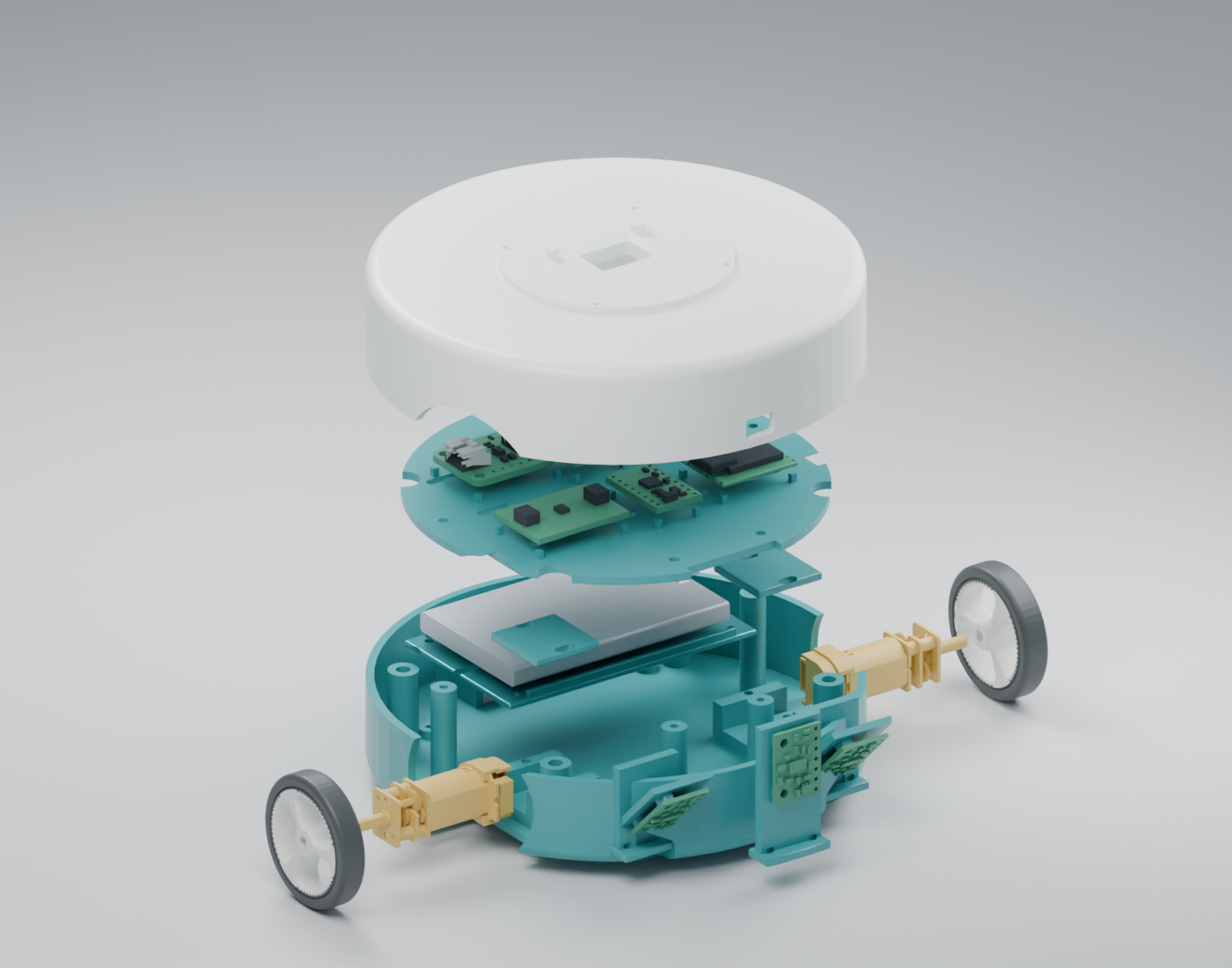
A compact two-wheel platform with a rear ball caster and a removable body interface. The screen, arm servos and voice hardware live in the upper character.
114 × 114 mmFootprint, wheels included
52.7 mmBase height, locating keys included
31 partsSupplier CAD, mounts and reconstructions
$209.13 USDPriced required hardware · USD
Current decision: the footprint is now flexible. A circular shell surrounds supplier-modelled drive hardware and electronics. Some component reconstructions, mounts and tabletop sensing still require physical validation.
Drag to rotate · scroll / pinch to zoom · select a part to inspect
02 / LOOK CLOSER
Review images & video
Rendered from the actual CAD
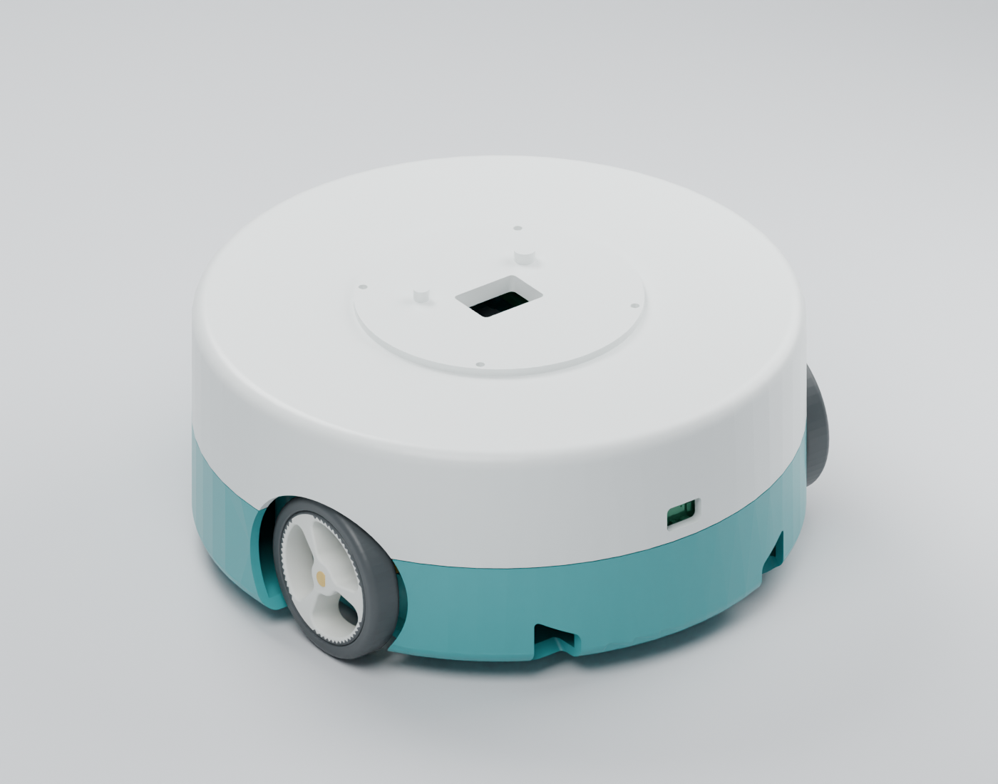
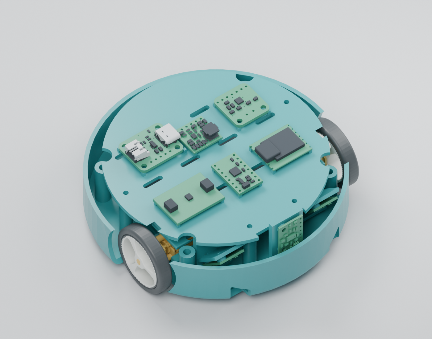
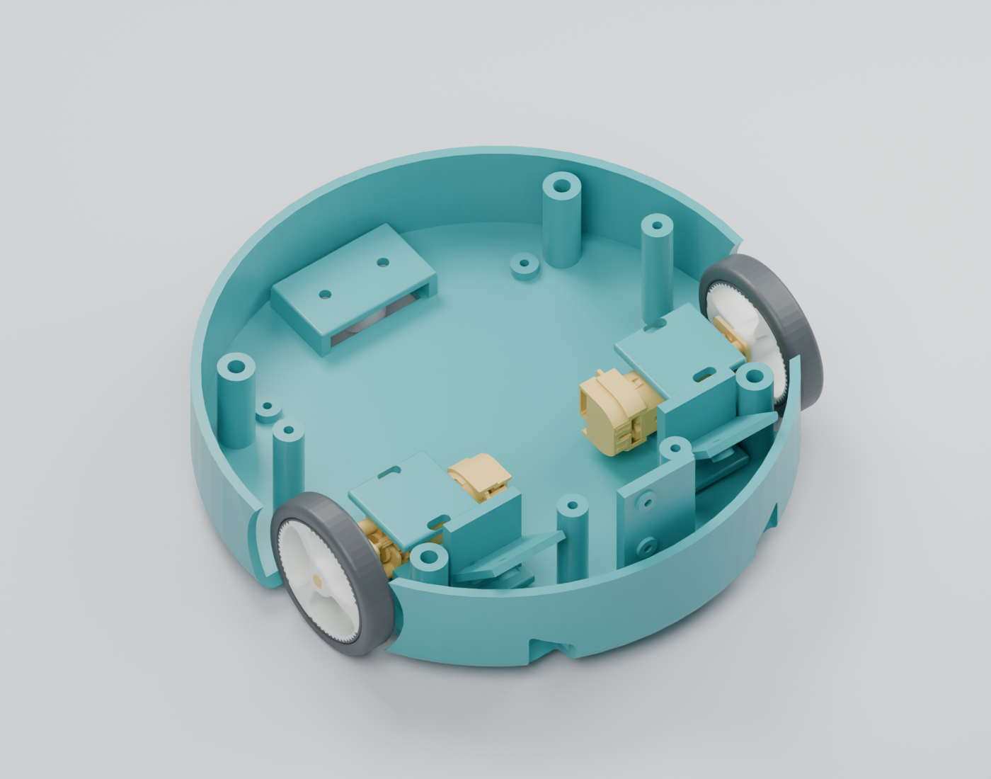
Common baseRounded shell and keyed top dockElectronics layoutSupplier boards above a low battery trayDrive bayTwo independent motors and passive casterUpper hardware carrierScreen and servos belong to the removable bodyExploded assemblyShells, trays, battery and drive partsTurntable360° rendered review · Download MP4
SENSOR LAYOUT
Obstacles ahead. Floor beneath.
Three small optical carriers
One VL53L1X looks forward. Two VL53L4CD boards look 45° forward/down from the front corners. Each board is about 13 × 18 mm. Separate views avoid asking one reading to distinguish an obstacle from the floor.
At an 18 mm sensor height, the nominal floor spot is 18 mm forward of each sensor. The nearest edge of the typical field of view lies about 36 mm ahead of the drive contact line. Actual detection and stopping distance must be measured.
These front sensors leave reverse and turning blind spots. Floor reflectivity, mixed edge returns and stale readings need testing. Browser cones illustrate direction and nominal field of view; their lengths are shortened for display and do not show maximum range. They are not validated protection.
USD prices checked 29 September 2026. Three ToF sensors are included. Encoder cables remain unpriced. Shipping, tax, PCB work and the cosmetic character body are excluded. Allowances are estimates, not supplier quotes.
Robot components, vendor links and prices
Component
Location
Qty
Unit USD
Total USD
Availability / note
Loading component list. The PDF is also available above.
Browse individual parts — STEP files and printable STLs
05 / DESIGN RECORD
Decisions & next steps
Established in this model
114 mm circular shell; original footprint limit relaxed.
Official STEP for the main drivetrain, power boards, battery, sensors and speaker.
32 mm drive wheels, rear caster and 4 mm shell ground clearance.
Four M2 body screws on a 36 mm square, asymmetric keys and connector opening.
Screen and arm servos remain in the removable upper hardware carrier.
One forward sensor plus two front-corner sensors angled 45° down.
Still to resolve
Measure bought parts and verify backorder delivery dates.
Confirm XIAO, IMU, servo, LCD and microphone reconstructions against samples.
Finish positive PCB and servo retention; print fit coupons.
Validate battery/current peaks, charge isolation, GPIO and body connector.
Measure braking and cliff sensing. Front sensors do not protect reversing or all turn paths.
29 SEP 2026 · V0.2
Circular base with supplier CAD, encoder motors and separate obstacle/cliff sensing. The user relaxed the earlier size limit so packaging can follow the hardware. Review the archived MB01 v0.1 →
Prototype, not a manufacturing release. Detailed confidence and residual fit limitations are included with each part and in the design notes. No runtime, payload or tabletop-safety rating is claimed.